Specular surfaces
 |
Rama
physically-based lighting Specular surfaces |
Like for the diffuse case, this is given by an integral over the infinitesimal elements of the light sources, which cannot be computed analytically. We could evaluate this integral numerically at render time, but this would be too costly for real-time rendering, and could also lead to discretization artifacts. Instead, we show here that, with some "reasonable" approximations (i.e., approximations yielding almost no perceptually visible differences in the final images), the integral can be approximated with a simple analytic expression with precomputed parameters.
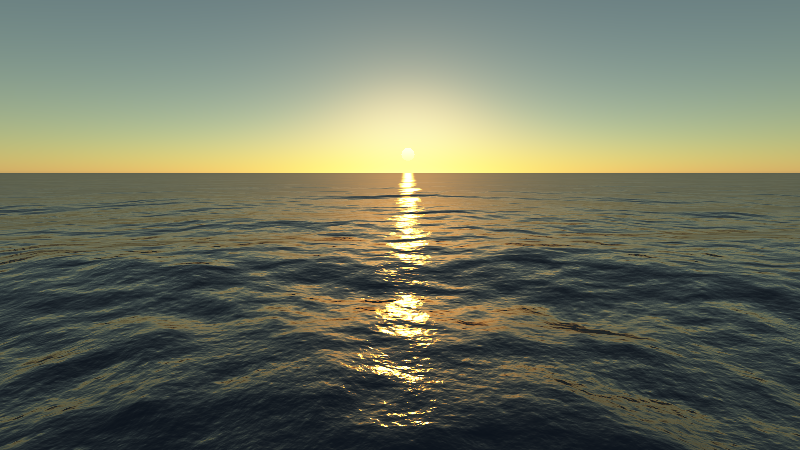
Specular surfaces can be modeled with many different BRDF models. The Phong model is one example, but it is not physically-based and gives very unrealistic results when applied to water surfaces (see Fig. 1). Since the only specular surface in our Rama model is the cylindrical sea, we want to use a physically-based BRDF giving good results for water surfaces. We chose to use the isotropic Ward BRDF, because it gives results which are quite close to a reference BRDF for water surfaces (the Ross et al. BRDF, see "Detailed analytical approach to the gaussian surface bidirectional reflectance distribution function specular component applied to the sea surface". Journal of Optical Society of America A 22, Nov. 2005). See Fig. 1.


Since the Rama light sources are very thin ($100\,m$, compared to their length of about $10\,km$), our very first approximation is to model them with line segments, instead of with a rectangular surface.
Then consider a linear light centered at $\bs$, of normal $\bn_s$, of width $w$ and length $2l$ and emitting a radiance $L_0$ in all directions of the upper $\bn_s$ hemisphere. We want to compute the light emitted by this source which is reflected towards $\bv$ by a specular surface patch centered at $\bp$, of normal $\bn$. If $\bv\cdot\bn<0$ or $(\bp-\bs)\cdot\bn_s<0$ this is 0. Otherwise, using the BRDF definition and the isotropic Ward BRDF, this is given by \begin{equation} \begin{split} L_{LS}(\bp,\bn)&=\int\color{red}{L_i}\color{green}{\mathrm{f_r}}\color{blue}{\cos\theta_i}\diff\omega_i\\ &=\int_{x_0}^{x_1} \color{red}{L_0\mathfrak{t}(\bs(x),\bp)V(\bs(x),\bp)}\color{green} {\frac{F(\bv\cdot\bh(x))\exp\left(-\frac{\tan^2\alpha(x)}{\sigma^2}\right)}{4\pi\sigma^2\sqrt{(\bl(x)\cdot\bn)(\bv\cdot\bn)}}}\color{blue}{\bl(x)\cdot\bn}\,\left(-\bl(x)\cdot\bn_s\right)\frac{w\diff x}{l^2(x)}\\ &=\frac{wL_0}{4\pi\sigma^2}\int_{x_0}^{x_1} \mathfrak{t}(\bs(x),\bp)V(\bs(x),\bp)F(\bv\cdot\bh(x))\sqrt{\frac{\bl(x)\cdot\bn}{\bv\cdot\bn}}\exp\left(-\frac{\tan^2\alpha(x)}{\sigma^2}\right)\,\left(-\bl(x)\cdot\bn_s\right)\frac{\diff x}{l^2(x)} \end{split}\label{eq:exact} \end{equation} where
This integral is too complicated to have an analytic solution. It also depends on too many parameters to be precomputed for all possible values. And computing this integral numerically at each pixel at render time would be way too costly. However, we show here that if we assume that $\sigma^2 \ll 1$, then with some "reasonable" approximations (i.e., approximations yielding almost no perceptually visible differences in the final images), we can compute this integral efficiently at runtime. We derive our method using 3 steps, detailed below:
Then, instead of using $\beta$, we can use $\phi$, the angle between $\bl(\beta)$ and the orthogonal projection of $\bv$ on the plane containing $\bp$ and the light source (see Fig. 2). Note that $\phi$ and $\beta$ differ only by a constant, which yields immediately: \begin{equation} L_{LS}=\frac{wL_0}{4\pi\sigma^2d}\int_{\phi_0}^{\phi_1} \mathfrak{t}(\bs(\phi),\bp)V(\bs(\phi),\bp)F(\bv\cdot\bh(\phi))\sqrt{\frac{\bl(\phi)\cdot\bn}{\bv\cdot\bn}}\exp\left(-\frac{\tan^2\alpha(\phi)}{\sigma^2}\right)\left(-\bl(\phi)\cdot\bn_s\right)\diff \phi \end{equation}
We can also remove the visibility term $V$, by restricting the integral to the subset of $[\phi_0,\phi_1]$ where $V$ is equal to $1$. In general this subset is hard to compute, but in the case of Rama's cylindrical sea, where the main occluder is the $500\,m$ tall south cylindrical wall (neglecting the Manhattan buildings, much smaller), we show in the Shadows section that it is a simple sub-interval $[\phi'_0,\phi'_1]$ which can be computed analytically.
We can now use the hypothesis we made at the beginning, namely that $\sigma^2 \ll 1$ (in practice we use $\sigma^2<0.02$). Let's note $\Phi$ the value of $\phi$ such that $\alpha(\phi)$ is minimal. Then our hypothesis means that the exponential term in the integrand vanishes very quickly when $\phi$ is not very close to $\Phi$. Thus the value of the remaining terms only matters for $\phi\approx\Phi$. And these terms do not vary as quickly as the exponential when $\phi$ varies, which means that we can see them as constant and move them outside the integral, which gives: \begin{equation} L_{LS}(\bp,\bn)\approx\frac{wL_0}{4\pi\sigma^2d}\mathfrak{t}(\bs(\Phi),\bp)F(\bv\cdot\bh(\Phi))\sqrt{\frac{\bl(\Phi)\cdot\bn}{\bv\cdot\bn}}\left(-\bl(\Phi)\cdot\bn_s\right)\int_{\phi'_0}^{\phi'_1} \exp\left(-\frac{\tan^2\alpha(\phi)}{\sigma^2}\right)\diff \phi \end{equation}
In practice we found that we could simplify these constant terms even further, using the $\phi$ coordinate of the light source center $\bs$, noted $\phi_s$, instead of $\Phi$, and removing the square root term completely: \begin{equation} L_{LS}(\bp,\bn)\approx\frac{wL_0}{4\pi\sigma^2d}\mathfrak{t}(\bs,\bp)F(\bv\cdot\bh(\phi_s))\left(-\bl(\phi_s)\cdot\bn_s\right)\int_{\phi'_0}^{\phi'_1} \exp\left(-\frac{\tan^2\alpha(\phi)}{\sigma^2}\right)\diff \phi\label{eq:approx1} \end{equation}
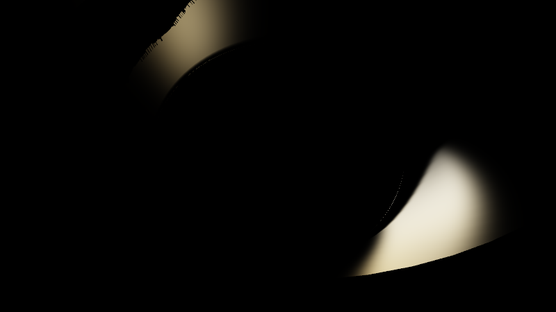
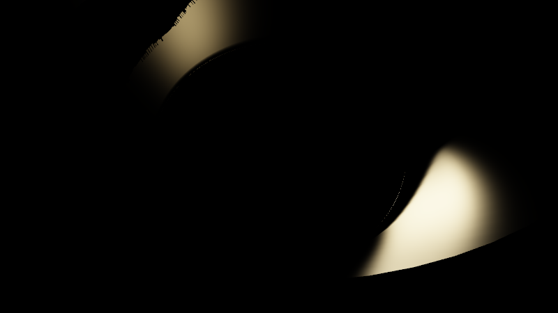
This can be seen in Fig. 3, which compares the specular reflection of a single linear light source on Rama's cylindrical sea (supposed perfectly cylindrical here, i.e., without waves, but with a roughness $\sigma^2=0.02$) obtained with Eq. \eqref{eq:exact} vs. Eq. \eqref{eq:approx1}.


The $\tan^2\alpha(\phi)$ term in the exponential can be rewritten as $1/\cos^2\alpha(\phi)-1$, which is also equal to $1/(\bh\cdot\bn)^2-1$. From the definition of the half vector $\bh$ we have \begin{align} (\bh\cdot\bn)^2&=\frac{((\bl+\bv)\cdot\bn)^2}{\Vert\bl+\bv\Vert^2}=\frac{(\bl\cdot\bn+\bv\cdot\bn)^2}{(\bl+\bv)\cdot(\bl+\bv)}=\frac{(\bl\cdot\bn+\bv\cdot\bn)^2}{2(1+\bl\cdot\bv)}\\ \end{align} which gives: \begin{equation} \exp\left(-\frac{\tan^2\alpha(\phi)}{\sigma^2}\right)=\exp\left[-\frac{1}{\sigma^2}\left(\frac{2(1+\bl\cdot\bv)}{(\bl\cdot\bn+\bv\cdot\bn)^2}-1\right)\right] \label{eq:gauss1} \end{equation}
Let us now introduce, without loss of generality, a coordinate system $(u,v,w)$ such that $\bp$ is at the origin, $\bp$ and the light source are in the $u,v$ plane, and the orthogonal projection of $\bv$ on this plane is parallel to the $u$ axis, and oriented in the same way (see Fig. 2). We then note $\theta_v$ (resp. $\theta_n$) the angle between the $w$ axis and $\bv$ (resp. $\bn$). We also note $\phi_n$ the angle between the projections of $\bv$ and $\bn$ on the $u,v$ plane. In this coordinate system, we have \begin{equation} \bv=\left[\begin{array}{c}\sin\theta_v\\0\\\cos\theta_v\end{array}\right],\quad \bn=\left[\begin{array}{c}\cos\phi_n\sin\theta_n\\\sin\phi_n\sin\theta_n\\\cos\theta_n\end{array}\right],\quad \bl=\left[\begin{array}{c}\cos\phi\\\sin\phi\\0\end{array}\right] \end{equation}
Substituting this in Eq. \eqref{eq:gauss1} we find that the integral we have to compute is \begin{align} W&\eqdef\int_{\phi'_0}^{\phi'_1} \exp\left(-\frac{\tan^2\alpha(\phi)}{\sigma^2}\right)\diff \phi\label{eq:gauss2}\\ &=\int_{\phi'_0}^{\phi'_1} \exp\left[-\frac{1}{\sigma^2}\left(\frac{2(1+\sin\theta_v\cos\phi)}{(\sin\theta_n\cos(\phi-\phi_n)+\cos\theta_v\cos\theta_n+\sin\theta_v\sin\theta_n\cos\phi_n)^2}-1\right)\right]\diff \phi \end{align}
It is clear that the integrand does not have an analytic indefinite integral, and thus can not be computed analytically. Also this indefinite integral depends on 4 parameters ($\theta_v,\theta_n,\phi_n,\sigma$), which means that we would need a 5D table to precompute all these functions. This is too much for practical applications, so we must find another solution.
Let us now consider $\bhb(\phi)$, the projection of $\bh(\phi)$ in this tangent plane. As $\phi$ varies, this point describes a curve in this tangent plane. Thus, the integral in Eq. \eqref{eq:gauss2} is the integral of a 2D Gaussian along a curve. Note that, from the definition of $\Phi$ above, $\bhb(\Phi)$ is the closest point to $\bn$ along the curve, and the vector from $\bn$ to $\bhb(\Phi)$ is orthogonal to the curve.
At this point we can make another use of our hypothesis, namely that $\sigma^2\ll 1$. This hypothesis means that the 2D Gaussian in the tangent plane to $\bn$ is very narrow (i.e., vanishes very quickly when the distance to $\bn$ increases). In other words, only the points along the $\bhb(\phi)$ curve that are the closest to $\bn$ contribute significantly to the integral in Eq. \eqref{eq:gauss2}. Said otherwise, only a small part of the curve around $\bhb(\Phi)$ contributes to the result. And since this part is small, we can approximate it with its first order approximation, i.e., a straight line. This approximation allows us to use the Pythagorean theorem in the tangent plane, yielding: \begin{equation} \exp\left(-\frac{\tan^2\alpha(\phi)}{\sigma^2}\right)=\exp\left(-\frac{\Vert\bhb(\phi)-\bn\Vert^2}{\sigma^2}\right)\approx\exp\left(-\frac{\Vert\bhb(\Phi)-\bn\Vert^2+\Vert\bhb(\phi)-\bhb(\Phi)\Vert^2}{\sigma^2}\right) \end{equation} The first norm is equal to $\tan\alpha(\Phi)$, a constant, and the second one can be approximated with it's first order approximation (again, because only the points $\bhb(\phi)$ near $\bn$, i.e., only the values of $\phi$ near $\Phi$, contribute to the integral): $\Vert\bhb(\phi)-\bhb(\Phi)\Vert\approx k|\phi-\Phi|$, where $k$ is the derivative of $\Vert\bhb(\phi)-\bhb(\Phi)\Vert$ at $\Phi$. The final result is \begin{equation} W\approx\exp\left(-\frac{\tan^2\alpha(\Phi)}{\sigma^2}\right)\int_{\phi'_0-\Phi}^{\phi'_1-\Phi} \exp\left(-\frac{k^2}{\sigma^2}\phi^2\right)\diff \phi=\frac{\sqrt{\pi}\sigma}{2k}\exp\left(-\frac{\tan^2\alpha(\Phi)}{\sigma^2}\right)\left[\mathrm{erf}\left(\frac{k}{\sigma}\phi\right)\right]_{\phi'_0-\Phi}^{\phi'_1-\Phi}\label{eq:final} \end{equation}
In other words, using some approximations which are valid under our hypothesis $\sigma^2\ll 1$, the integral can be computed analytically, as we wanted, provided we know the values of $\Phi$ and $k$. Unfortunately $k$ depends on $\Phi$, and $\Phi$ can not be computed analytically (it is the solution of $\diff\tan^2\alpha(\phi)/\diff\phi=0$, a very complex equation without analytic solutions). However, it is easy to see that $\Phi$ and $k$ depend on "only" 3 parameters: $\theta_v$, $\theta_n$ and $\phi_n$. It is thus possible to precompute them with "slow" numerical solving methods and to store the results in a 3D table (in practice we also precompute $\tan^2\alpha(\Phi)$ to save runtime computations).
This is what we did, using $\cos\theta_v$, $\cos\theta_n$ and $\phi_n$ as parameters (we found this was giving better interpolated results than when using $\theta_v$, $\theta_n$ and $\phi_n$ directly). Since it is always possible to choose the coordinate system $(u,v,w)$ such that $\theta_v>0$, and since changing $\phi_n$ in $-\phi_n$ changes $\Phi$ in $-\Phi$ (and leaves $k$ unchanged), we can restrict the ranges for $\cos\theta_v$, $\cos\theta_n$ and $\phi_n$ to $[0,1]\times[-1,1]\times[0,\pi]$ respectively. In the following we use $32\times 128 \times 64$ samples respectively, which gives a 3 MB table (using 32 bits floats).
float erf(float x) {
  // Precise approximation, but this precision is not really needed.
  // return sign(x) * (1.0 - exp(-x * x) / (1.1595 * abs(x) + sqrt(1.0 + 0.38 * x * x)));
  // Less precise but faster and good enough approximation.
  return sign(x) * (1.0 - exp(-x * x) / (1.3 * abs(x) + 1.0));
}
We can also define a function to fetch the precomputed $k$, $\Phi$ and $\tan^2\alpha(\Phi)$ values for given values of $\cos\theta_v$, $\cos\theta_n$ and $\phi_n$. We just need to lookup a 3D texture containing these values, while taking care of negative $\phi_n$ values (the opposite of $\Phi$ must be returned in this case):
// Fetch the Phi, k and tan^2 alpha(Phi) precomputed values for the
// given cosThetaV, cosThetaN and phiN parameters. Return them in this
// order in a vec3.
vec3 wardParams(float cosThetaV, float cosThetaN, float phiN) {
  float s = sign(phiN);
  vec3 u = vec3(cosThetaV, cosThetaN * 0.5 + 0.5, s * phiN / PI);
  const vec3 RES = vec3(32.0, 128.0, 64.0);
  u = 0.5 / RES + u * (1.0 - 1.0 / RES);
  return texture3D(wardSampler, u).rgb * vec3(s, 1.0, 1.0);
}
Using these two functions we can now provide a function to evaluate Eq. \eqref{eq:gauss2} using the approximation in Eq. \eqref{eq:final}. Note a subtelty here, compared to the above equations: the original "Gaussian" in Eq. \eqref{eq:approx1} is periodic in $\phi$ with a $2\pi$ period, but the approximation in Eq. \eqref{eq:final} is not. To get correct results we need to restore this periodicity, and we do this with the norm function inside the erf calls. But this can invert the order of the integration bounds, which is why we use an absolute value in the last line of the wardIntegral function:
// Return the angle a clamped to [-pi:pi] by adding to it the
// appropriate multiple of 2pi.
float norm(float a) {
  return a - 2.0 * PI * floor(a / (2.0 * PI) + 0.5);
}

// Evaluate Eq. 12 (divided by 4 pi sigmaSq) to compute an approximation
// of the integral in Eq. 9 (integrating some factors from Eq. 5).
float wardIntegral(float cosThetaV, float cosThetaN, float phiN,
                   float sigmaSq, float phi0, float phi1) {
  vec3 wardParams = wardParams(cosThetaV, cosThetaN, phiN);
  float Phi = wardParams.x;
  float k = wardParams.y;
  float tanSq = wardParams.z;
  float oneOverSigmaSq = 1.0 / sigmaSq;
  float oneOverSigma = sqrt(oneOverSigmaSq);
  float v0 = erf(oneOverSigma * k * norm(phi0 - Phi));
  float v1 = erf(oneOverSigma * k * norm(phi1 - Phi));
  return exp(-oneOverSigmaSq * tanSq) * abs(v1 - v0) * oneOverSigma /
      (8.0 * sqrt(PI) * k);
}
We can finally implement the function computing Eq. \eqref{eq:approx1} (without the light intensity, transmittance and Fresnel terms, which are supposed to be handled by the caller of this function). The main role of this function is to construct the basis vectors of the coordinate system introduce above, to use them to compute the $\cos\theta_v$, $\cos\theta_n$ and $\phi_n$ parameters, as well as the integration bounds, and finally to call the wardIntegral function with these arguments:
// Compute the light emitted by a linear light source centered at s,
// aligned with the x-axis and extending between x=u.x and x=u.y which
// is reflected by a specular surface patch at the origin, of normal n,
// towards a viewer in direction v. It is assumed that the specified
// light is fully visible from the surface patch (for this the u vector
// should be computed with visibleLightSegment).
// The light intensity, the atmospheric transmittance and the Fresnel
// factor are not taken into account.
float specular(vec3 s, vec2 u, vec3 n, vec3 v) {
  float d = length(s.yz);
  // Compute the basis vectors of the u,v,w coordinate system
  float side = sign(s.y * v.z - s.z * v.y);
  vec3 ew = vec3(0.0, -s.z, s.y) * side / d;
  vec3 eu = normalize(v - ew * dot(v, ew));
  vec3 ev = cross(ew, eu);
  // Compute cos(thetaV), cos(thetaN) and phiN
  float cosThetaV = dot(v, ew);
  float cosThetaN = dot(n, ew);
  float phiN = atan(dot(n, ev), dot(n, eu));
  // Compute the bounds of the integration interval
  vec3 l0 = vec3(u.x, s.yz);
  vec3 l1 = vec3(u.y, s.yz);
  float phi0 = atan(dot(l0, ev), dot(l0, eu));
  float phi1 = atan(dot(l1, ev), dot(l1, eu));
  // Compute the lighting integral
  return wardIntegral(cosThetaV, cosThetaN, phiN, sigmaSq, phi0, phi1) / d;
}


and then for the 6 linear light sources (using a smaller exposure):


